
Graflex Lightsaber Part 6: Final
With everything complete, it is time to start final assembly of my lightsaber. This time, with the added bonus of trying to fit about 25 feet of wiring and additional electronics.
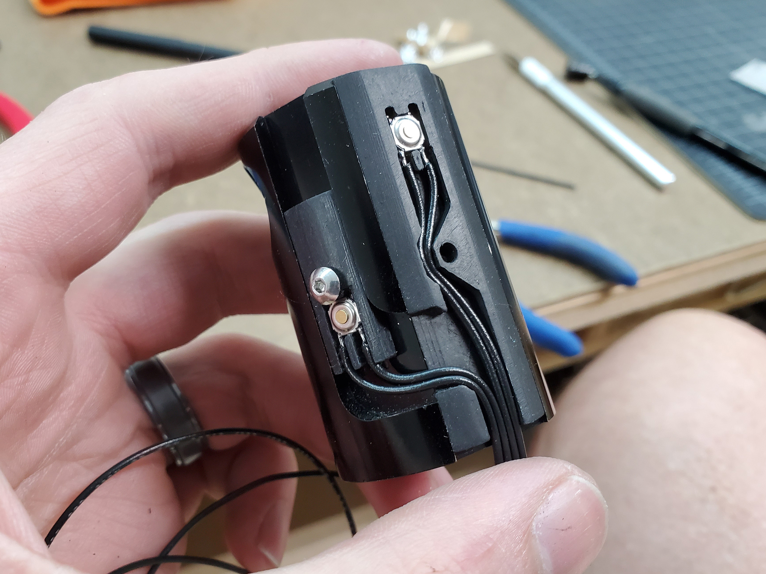
The first thing to do was work on the activator and options switches. The switches I ended up choosing are micro surface-mount switches, which are intended for use on circuit boards. They are held in place by a small piece of 3M double stick adhesive. Additionally, they are mechanically held in place by my 3D printed housings. I used 26 AWG wire throughout the whole project.

The main LED for the bade in a Naigon Electronic’s Cree RGB which is made specifically for the Naigon Igniter board I am using. The LED assembly is held in place by a thermal pad and is attached to this large aluminum heatsink. This type of LED expends a ton of heat.

To ensure everything gets wired up to the control board correctly, I had to color code each wire. When everything in installed, there will be 20 different wires running through the chassis, so it will get complicated.
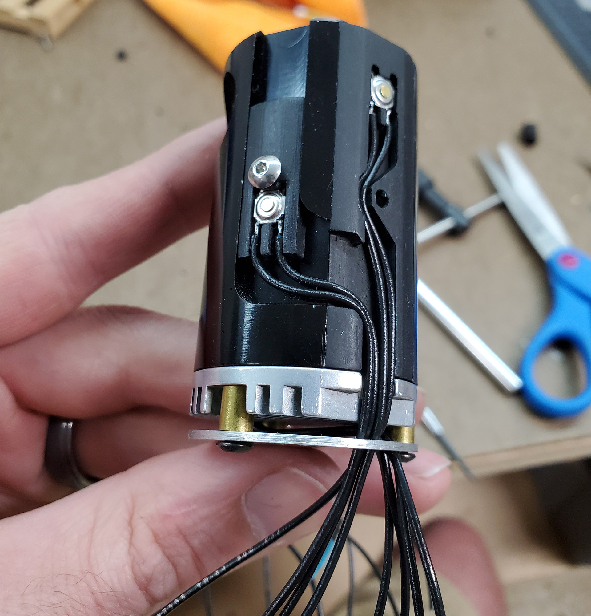
Here is the completed emitter assembly. 4 wires for red, green, blue, and common ground on the LED, and 2 wires for each switch.

Next, I wired up and installed the 10mm shaftless vibration motor, and 3w 20mm speaker. It was at this point that I realized I needed the thread each wire individually though the chassis. If any of the wires twisted around or crossed over another it would cause the whole bundle to bind. All the wires needed to be perfectly parallel.

The hardest part up to this point was getting all the wires to pass cleanly through the hollow tubes in the crystal chamber assembly.
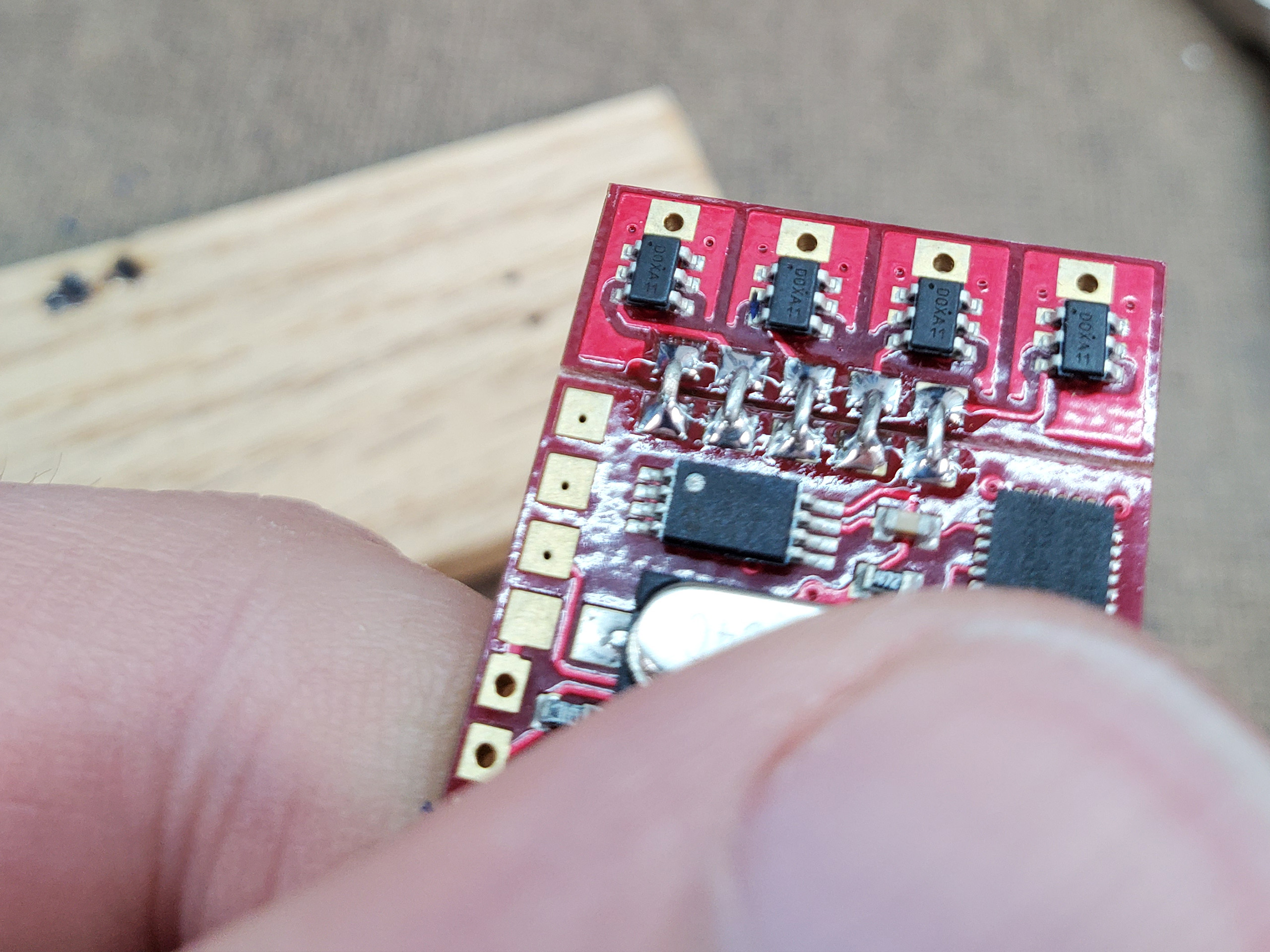
I unfortunately did not take any pictures of wiring the battery assembly. I had a real hard time with this part because not only did I have to wire the battery contact, but also I had to install an inline charging point and kill switch. With all that done, I started working on the control board. The LED drivers are not wired into the board so I had to attach them with some small jumpers made from resistor legs.
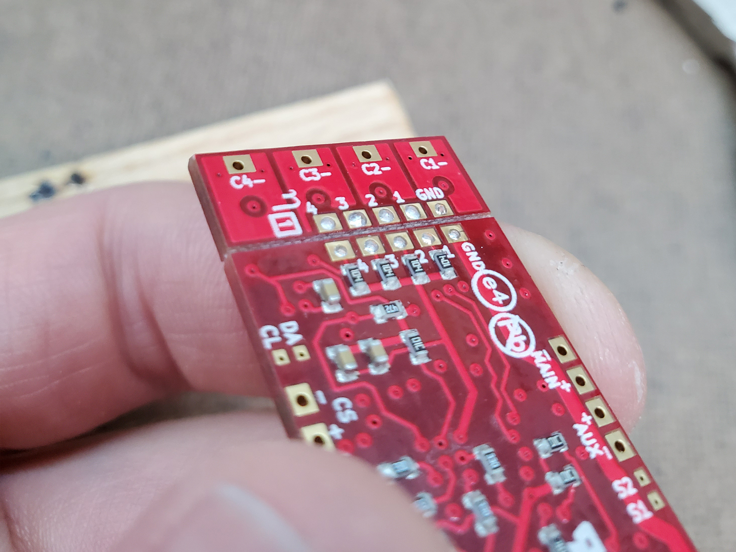
My best soldering job yet (pats self on back).

Here are all those wires from before neatly trimmed up and soldered to the control board. It was looking real clean until I had to wire up the crystal chamber LED. That LED required its own resistors. If I was smart, I would have used some small surface mount 0805 or 0603s on the LED board. Instead, I just wired some inline through-hole components and insulated them with some heatshrink tubing.

This is the completed assembly all wired up with my brass cover over the control board. Nothing left to do but install it in the Graflex body.
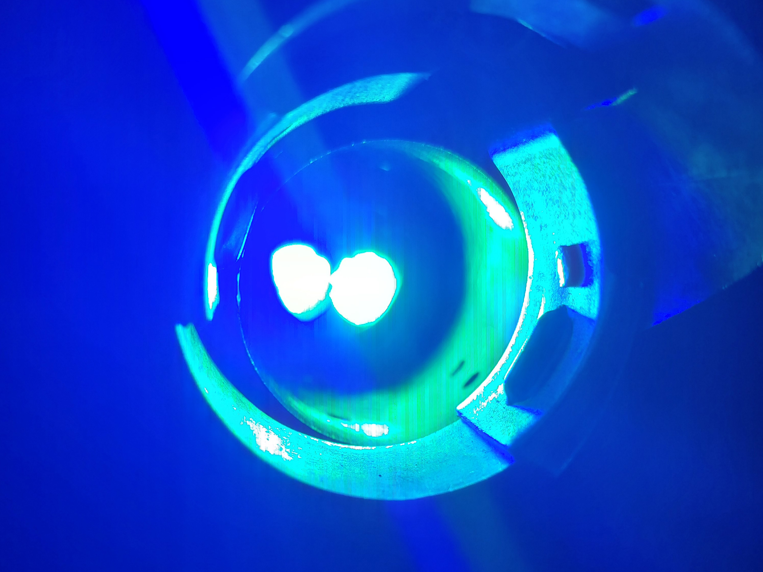
Here is a quick demo of the emitter LED. It is dangerously bright. You can see in the image, it is so bright that it is causing artifacts in my photograph.

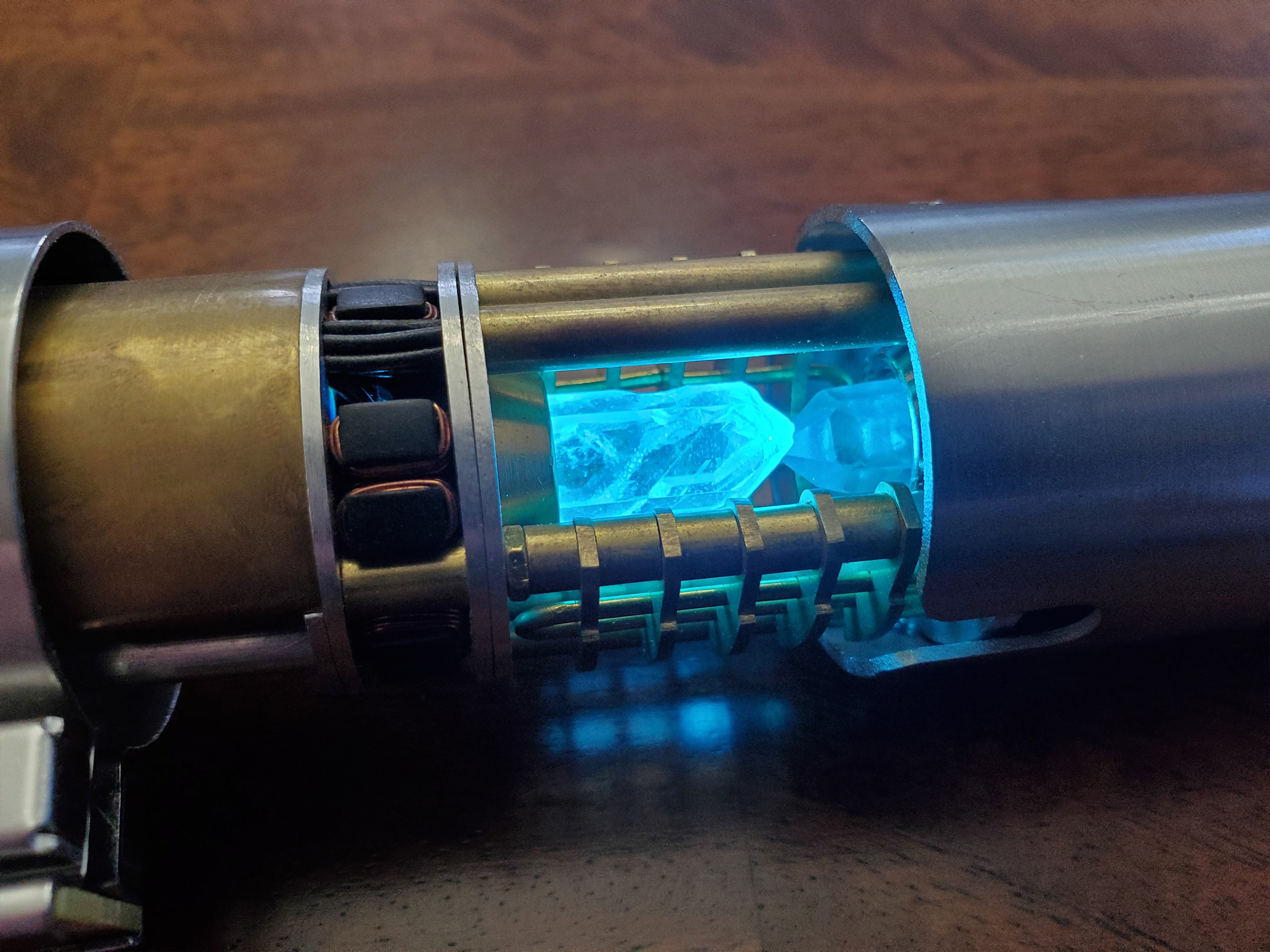
Last by not least is the ignited crystal chamber. Since the RGB LEDs are wired in parallel, the chamber glows whatever color the blade is set to. The only problem is the chamber has a very slight greenish tint. My guess is that either my resistor value for green is too low or my value for blue is too high, throwing off the mix. It isn’t terribly noticeable and maybe something to fix one day in the future.
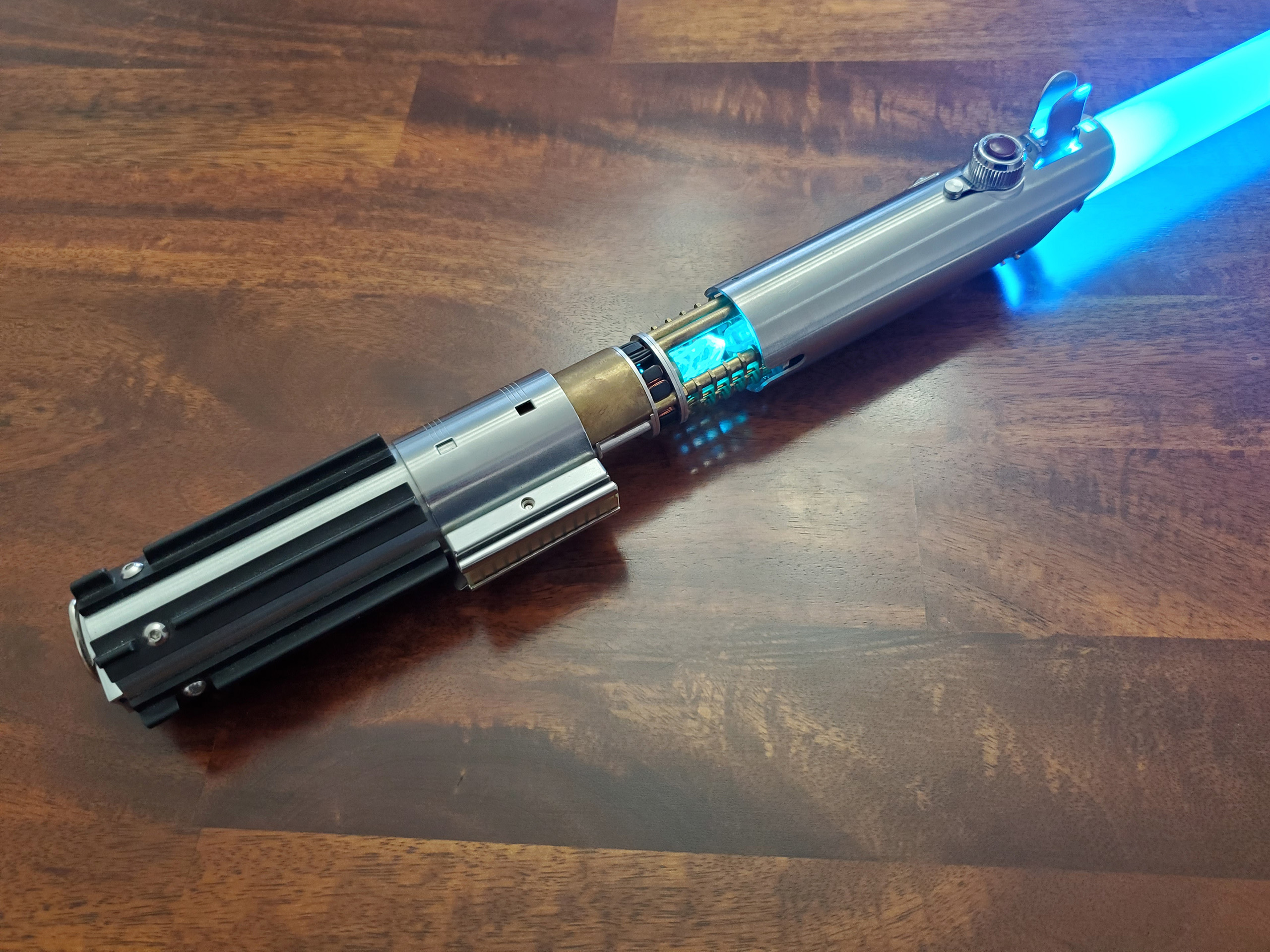

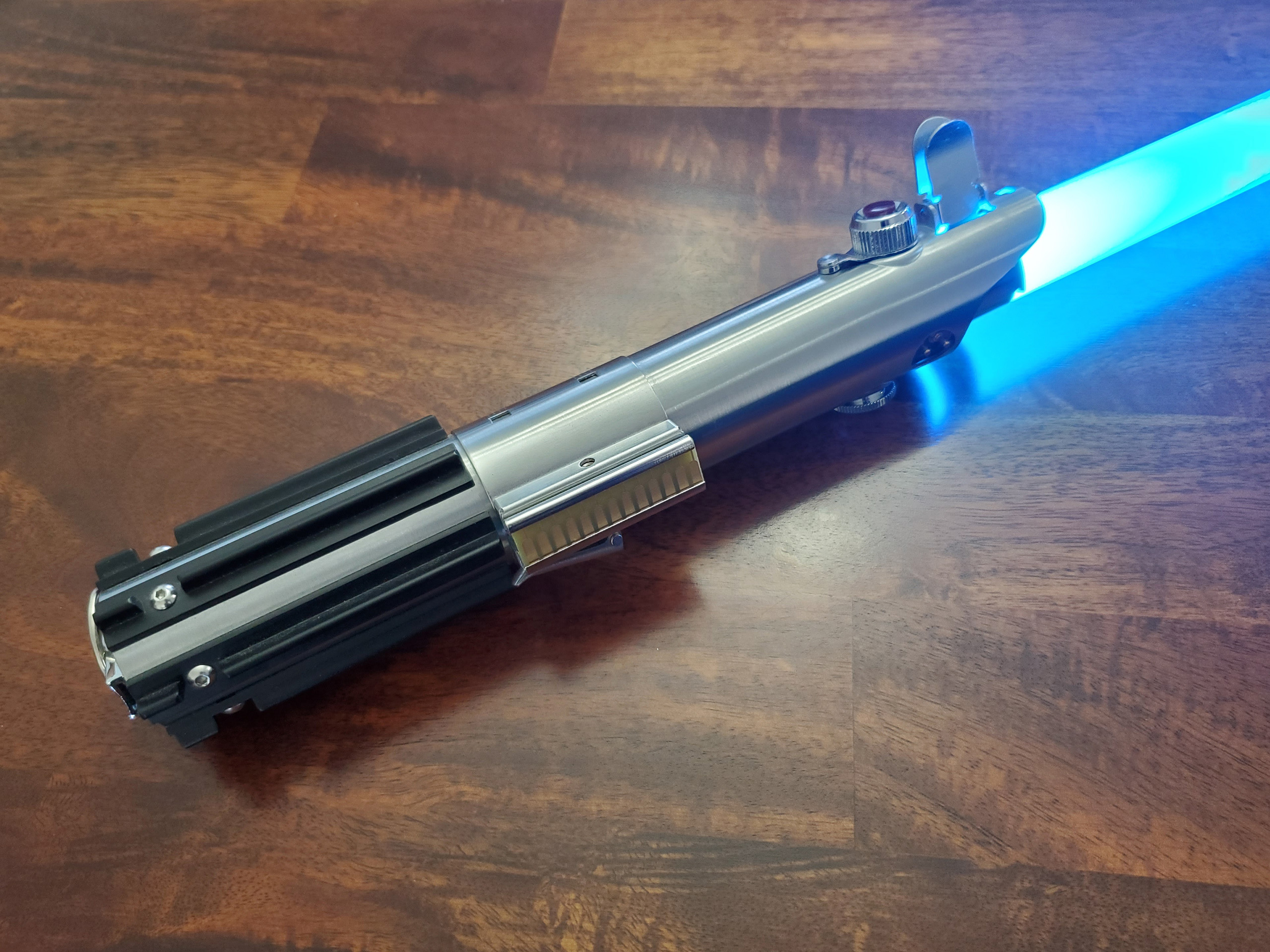
Here are a few quick glamour shots of my completed Skywalker Lightsaber.
I could not be happier with how it came out. It took WAY (years) longer than I expected to complete. Some of that was procrastination, and some of it was just lack of confidence and being overwhelmed. It was an excellent exercise in skill building at the very least.
I hope you enjoyed the build, and as always, thanks for looking!
Other parts of this project
◄ Graflex Lightsaber Part 1: Planning
◄ Graflex Lightsaber Part 2: More Planning
◄ Graflex Lightsaber Part 3: Test Assembly
◄ Graflex Lightsaber Part 4: Fabrication
◄ Graflex Lightsaber Part 5: Cleanup


Add a Comment
You must be logged in to post a comment.

Awesome build! Thanks for letting me tag along with you on the journey!