Graflex Lightsaber Part 3: Test Assembly
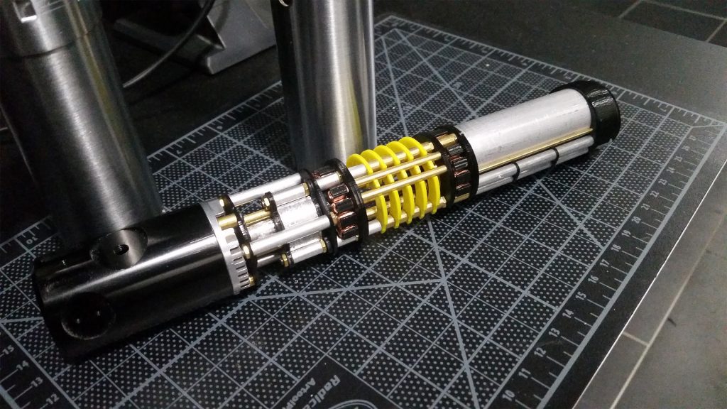
With all the planning complete, it is time to start on initial part fabrication and a test assembly of the chassis. For this test fitting, I am going to be using a combination of 3D printed and laser cut placeholder parts, and aluminum and brass components that will be used in the final assembly. I really just want to see what everything will look like assembled and make sure it actually fits inside the Graflex chassis.
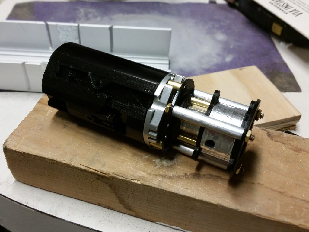
I started assembly by working from the emitter end. I 3D printed the rumble motor and speaker holder using black PLA. To make it look a little more presentable, I wrapped some of the flat surfaces in aluminum tape to give them a metal look. Personally, I think these look really bad. For the final version, I will either try printing these pieces using my resin printer, or print again in PLA using higher settings and sand/paint the parts. However, I am happy with the overall fit, and the look of the aluminum tube stock.

The temporary laser cut acrylic chassis disks are working great. The holes are a hair larger than I had spec’d out. This is because the laser cut ON the line instead of INSIDE the line, burning away a little bit of material. However, everything is well within 0.1mm probably closer to 0.05mm. It does make everything slide together a little easier though.

The next thing I printer were these coil pieces. They are indented to resemble the look of motor’s stator windings. I think they give a real electromechanical look to the whole saber. Instead of using the stators from a real motor, I made these from scratch so that they are the exact dimensions that I want. I printed the cores from black PLA, and used 0.5mm copper wire for the windings. You may notice some of the windings are missing. This is to give room for wires to pass through later on the final build. In the center of each stator is a plumbing faucet valve seat, which will be used to hold the saber “kyber”crystal in the future.

I apologize. I know this looks like a big jump in progress, but I was so carried away with assembling all the small brass and aluminum tube sections that I didn’t think to take any pictures. It was really easy to assemble too. Everything sits on 3 long 4-40 threaded steel rods, so it was just like string beads, basically stacking up parts on order. The whole process only took a few minutes. Everything is literally starting to come together. The complete prototype assembly looks exactly like my 3D model. The only discrepancy is the acrylic disks are ever so slightly thicker than the aluminum and brass stock that the final pieces will be made from. To mitigate this, I sanded each disk down a bit to reduce their thickness. They are close, but the completed prototype assembly is about 1.5mm longer than the final assembly will be.
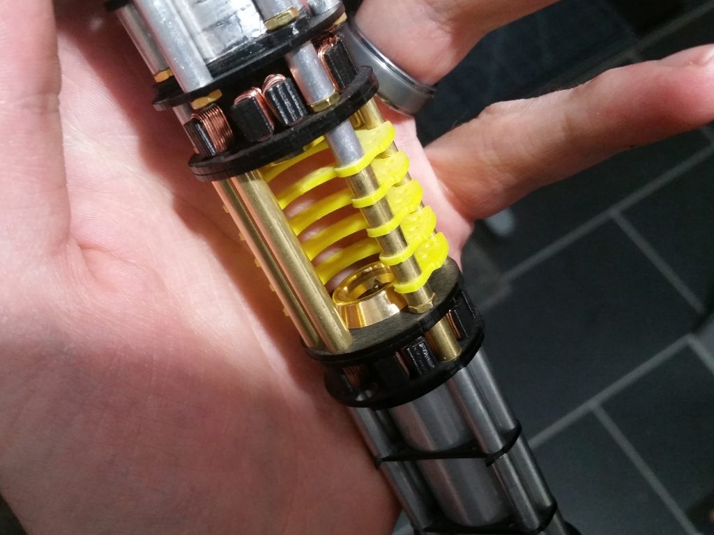
Here is a close up of the star of the build, the crystal chamber assembly. The bright yellow 3D printer parts will be replaced with hand machined brass parts on the final build.
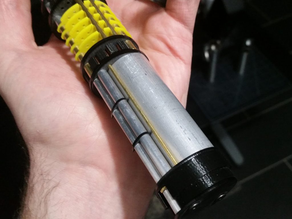
This is a close up of the electronics assembly. The large diameter aluminum tube will house the lithium ion battery, and the black 3D printed end cap will contain all the charging circuitry. The flat area resting against my palm is where the control board will eventually live.

Last, here is a picture of the chassis installed in the top half on the Graflex chassis. This is more or less how the saber will look when you remove the bottom to reveal the crystal chamber. You can also get a better view here of the flat control board area.

I also took this opportunity with everything assembled to put some of the finishing touches on the Graflex chassis. The Korbanth/Parks Graflex 2.0 kit came with a set of adhesive backed fins for the hilt. The screws (which are rivets on the screen used prop) are purely cosmetic. Unfortunately, they are about 3/16” too long and actually protrude into the chassis itself so I had to shorten them. To do this, I used the threaded screw cutter feature on my wire strippers. A lot of people don’t even know this feature exists, but it cuts screws and threaded rods flawlessly. Simply thread the screw into the cutter at the length you want it cut.

Snip the screw like you are using a pair of scissors.
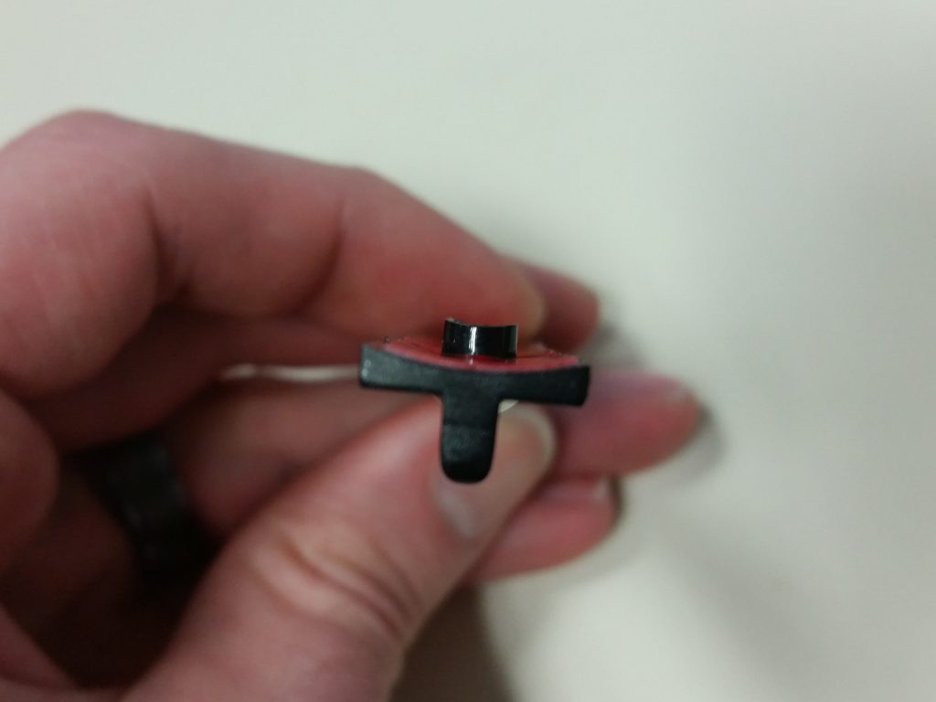
Here are the shortened fins, which now clear the inside of the Graflex body and won’t interfere with the chassis.

The next thing I did was purchase a 1” x 1.5” Blade Plug from https://krsabers.com/. I purchased this back in 2016 off their Etsy store. It was a great price, and great craftsmanship. I did have one small problem though. The tolerances of everything was too tight. The blade plug was exactly 1.000” diameter when measured with my calipers, and the blade holder was 1.002” – 0.998” depending on how you measured it. It is really hard to fit a 1” peg into a 1” hole. To fix the fitment, I just chucked the blade plug into my drill shaved off a few thousandths of material with some fine sand paper and polished up the new surface.
Now that I know everything fits, the next order of business is to get rid of all these temporary placeholder pieces and start machining parts out of metal.
Thanks for looking!
Other parts of this project
◄ Graflex Lightsaber Part 1: Planning
◄ Graflex Lightsaber Part 2: More Planning
► Graflex Lightsaber Part 4: Fabrication
► Graflex Lightsaber Part 5: Cleanup
► Graflex Lightsaber Part 6: Final


Would you be willing to sell your CAD model for your Graflex light saber chassis?
This is something I have thought about. To my current knowledge, the parts fit inside a Parks 2.0 body. I have not tried any other reproduction graflex or genuine graflex bodies. I would hate the sell something that may be functionally useless to a large percent of the saber community.